Project Overview
I went into this thinking I'd watch a couple YouTube videos, order some parts, and slap together a drone over a weekend. That is not what happened. What actually happened was months of going back and forth on component choices, waiting on shipments that seemed to take forever, teaching myself to solder without burning down the house, and slowly realizing that building a drone from scratch is more like building a small aircraft than snapping together Legos. This page documents the whole process as it actually unfolded — not a polished tutorial, but the real experience of someone figuring it out for the first time.
The finished quad runs a Volador II VD5 deadcat frame with iFlight XING2 2207 motors, a SpeedyBee F405 V4 stack handling flight control and ESC duties, and a DJI O4 Air Unit Pro for video transmission and 4K recording. An ExpressLRS receiver handles the control link. On paper that sounds like a clean, well-planned build. In practice, getting all of these parts to work together involved a lot of trial and error, a few components that didn't fit the way I expected, and more time staring at wiring diagrams than I'd like to admit.
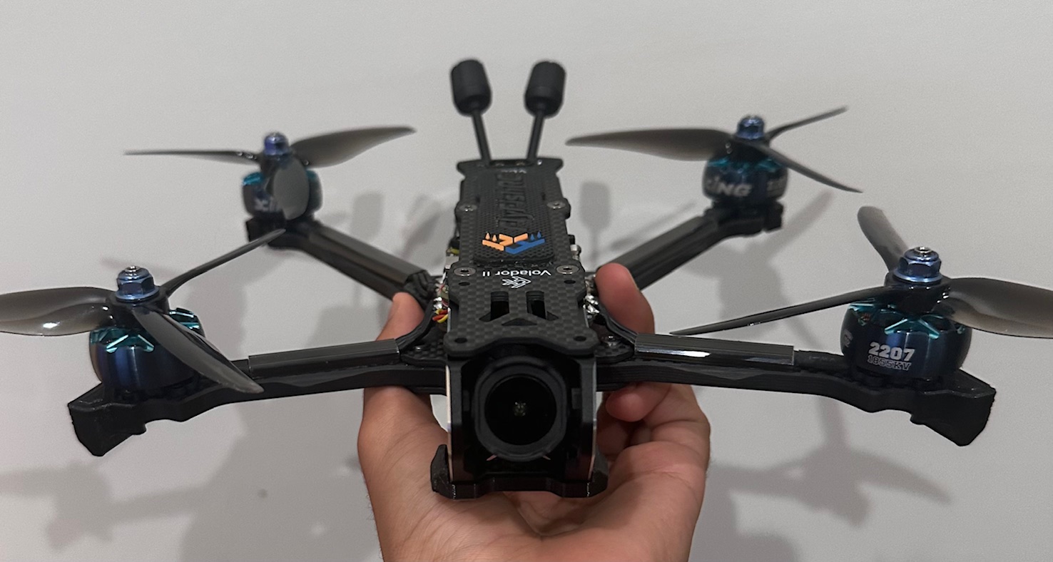
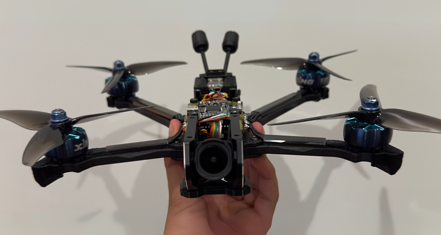
The end result after months of work — roughly 400 grams of carbon fiber, motors, and electronics that somehow came together into something that flies. Hover over the image to see the deadcat frame geometry from another angle.
Why This Particular Build?
The short answer is that I fell down a YouTube rabbit hole and couldn't climb back out. I'd been watching FPV freestyle and cinematic videos for weeks, and at some point, watching other people fly stopped being enough. The Volador VD5 frame caught my attention because the deadcat arm layout looked different from the standard X-frame designs that dominate the hobby — the front arms angle forward to keep the propellers out of the camera's field of view, which matters a lot for recording clean footage. The DJI O4 Pro was appealing because I didn't want to deal with the limitations of analog video on my first build, and having 4K onboard recording built into the video system meant one less separate component to worry about. The rest of the parts fell into place around those two decisions, though "fell into place" is doing a lot of heavy lifting considering how many spreadsheets I went through comparing specs.
What is an FPV Drone?
FPV stands for First-Person View, and the name describes the core experience pretty well. A camera mounted on the drone streams live video to a pair of goggles you wear, so you see what the drone sees in real time. It's the closest thing to actually being in the air without leaving the ground. Unlike the DJI Mavic-style camera drones most people are familiar with — which hover in place, avoid obstacles automatically, and basically fly themselves — FPV drones are manual machines. You control every movement with stick inputs. There's no obstacle avoidance, no GPS-assisted hovering (unless you set it up that way), and no safety net. If you let go of the sticks in acro mode, the drone keeps doing whatever it was doing. That's what makes it exciting, and also what makes it a skill you have to develop over time.
Real-Time Video Feed
A low-latency camera on the drone transmits live footage to goggles or a ground monitor. The delay between reality and what you see is measured in milliseconds — fast enough that it feels like you're sitting in the cockpit. Digital systems like DJI's O4 have made the image quality sharp enough that you can read text on signs from hundreds of feet away, which is a massive improvement over the static-filled analog feeds that were standard just a few years ago.
Speed & Manual Control
FPV quads are built light and powerful. A typical 5-inch build like mine can hit 80+ mph and accelerate hard enough that the G-forces would be uncomfortable if you were actually onboard. In acro mode, there's no auto-leveling — the drone responds directly to your stick inputs, which gives you full 3D freedom to do flips, rolls, inverted flying, and tight proximity maneuvers that would be impossible on a stabilized platform. The learning curve is steep, but that's part of the appeal.
Racing, Freestyle & Cinematic
People use FPV drones for organized racing through gates and courses, freestyle flying where the goal is creative aerial tricks and smooth lines through interesting environments, and cinematic work where the raw agility of the platform lets you get camera angles that no traditional drone or helicopter could achieve. Some of the most impressive aerial footage you've seen in commercials and films was probably shot on an FPV rig.
FPV vs. Standard Camera Drones
Standard Camera Drones
Designed around ease of use and stability. GPS holds position, sensors prevent crashes, and the software handles most of the flying. You tell it where to go and it figures out how to get there safely.
Optimized for photography and videography. Gimbal-stabilized cameras, automated flight paths, subject tracking, and point-of-interest orbits. The goal is smooth, cinematic output with minimal pilot skill required.
Example: A DJI Mini or Mavic — you take it out of the box, pair it with your phone, and you're flying within minutes. The trade-off is that you're limited to what the software allows you to do.
FPV Drones
Full manual control with no guardrails. You are the autopilot. The flight controller keeps the motors spinning and interprets your stick inputs, but it won't stop you from flying into a tree or the ground. That freedom is exactly the point.
Immersive piloting through goggles. Instead of watching a phone screen from the ground, you're wearing goggles that fill your vision with a live feed from the drone's camera. The sense of speed and presence is completely different from flying line-of-sight.
Built from individual components, not bought off a shelf. Most FPV pilots build their own quads, choosing specific frames, motors, flight controllers, and video systems based on their flying style and performance goals. Every build is different.
Why Build Instead of Buy?
Understanding the Machine
When you assemble every component yourself, you understand how the whole system works — how the flight controller interprets gyro data, how ESCs regulate motor speed, how the video transmitter communicates with your goggles. That knowledge isn't just academic; it's what lets you diagnose problems in the field, swap out parts, and tune the quad to fly the way you want. If something breaks, you know exactly how to fix it because you're the one who put it together.
Tailored Performance
Pre-built FPV drones (known as BNFs or RTFs) are compromises designed to work for the broadest possible audience. Building your own lets you prioritize what matters to you — whether that's raw speed, smooth cinematic footage, durability for learning to fly, or lightweight efficiency for long-range cruising. You pick every single component, so the end result is exactly suited to your goals.
Practical Engineering Skills
Over the course of this build, I learned to solder, read wiring diagrams, use a multimeter, configure firmware, design and 3D-print custom parts, and troubleshoot electrical issues. These aren't abstract skills — they transfer directly to robotics, electronics repair, automotive work, and any other hands-on technical field. The drone is almost a byproduct of the education you get from building it.
The Bigger Picture
Building an FPV drone forces you to engage with electrical engineering, mechanical assembly, software configuration, and aerodynamics all in a single project. It's one of the few hobbies where you go from reading datasheets about motor KV ratings to physically flying the thing you built within the span of a few weeks. The problem-solving skills carry over to just about any technical discipline, and there's a satisfaction to flying something you wired and assembled yourself that buying a pre-built just can't match.
Tools Required
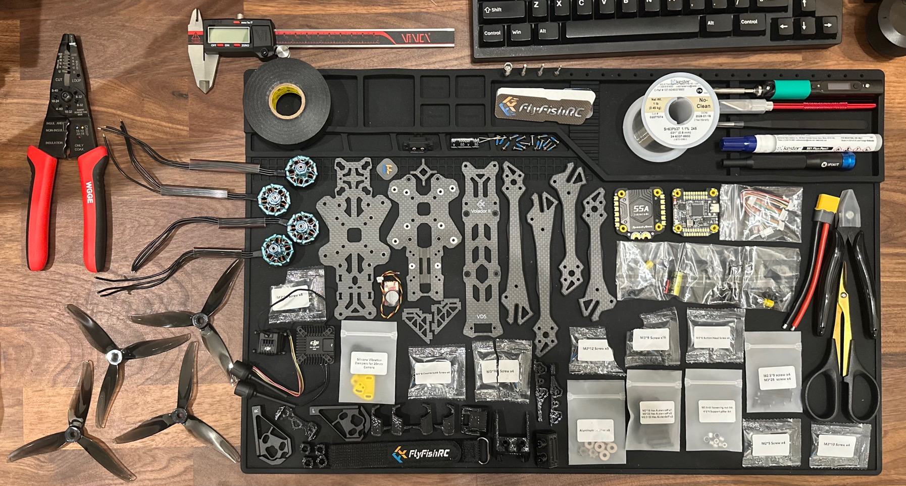
Before I started this build, the most complex tool I owned was a Phillips-head screwdriver from a kitchen drawer. I had this vague idea that building a drone required a soldering iron and maybe some wire strippers, and that was about it. Turns out the tool list is significantly longer than that, and trying to cut corners on tools is one of the fastest ways to make a build miserable. Every cheap or missing tool adds friction to the process, and that friction compounds over hundreds of small tasks. Here's the full set of tools I ended up using, along with honest notes on why each one mattered.
- Digital Caliper - VINCA DCLA-0605 - I used this constantly. Measuring standoff heights, checking whether components would physically fit inside the frame, verifying wire gauge — the caliper came out at almost every stage of the build. The capacitor fiasco from Week 4 would have been completely avoided if I'd measured the frame cutout before ordering parts.
- Soldering Iron - PINECIL Smart Mini Portable Soldering Iron - This was probably the single most important tool purchase. The PINECIL heats up in about 8 seconds, holds temperature precisely, and runs off USB-C power so you can even use it portably with a battery bank. I started with a cheap Amazon iron and the difference was night and day — the cheap one couldn't hold temperature, which meant cold joints and frustration. The PINECIL made soldering feel controlled instead of chaotic.
- Wire Strippers - KAIWEETS automatic wire strippers - Self-adjusting strippers that grip and strip wire in one squeeze. Before I had these, I was using a razor blade to strip wire, which was slow, inconsistent, and occasionally nicked the conductor underneath. These saved a surprising amount of time and gave clean strips every time.
- Flux Pen - Kester 951 No-Clean flux pen - Flux is what makes solder flow where you want it to instead of balling up and rolling away. The pen format is convenient because you can apply it precisely to a pad right before you solder. The "no-clean" part means you don't have to scrub the board afterwards, which is nice because the residue left behind is electrically inert.
- Solder - Kester 63/37 rosin core solder - The 63/37 tin-lead ratio is eutectic, meaning it transitions from solid to liquid at a single temperature (183°C) rather than having a "pasty" range. In practice, this means joints set quickly and cleanly. I tried cheap solder from Amazon first and the difference in joint quality was obvious. This is not the place to save five dollars.
- Tip Cleaner - Hakko 599B-02 wire-type cleaner - A coil of brass wire that you stab the iron tip into to clean off oxidized solder. The alternative is a wet sponge, but that rapidly cools the tip every time you touch it, which means the iron has to recover temperature before you can make the next joint. The brass cleaner doesn't have that problem.
- Screwdriver Set - iFixit Mako 64-piece precision bit set - Probably more bits than I needed for this one build, but the quality of the driver handle and the precision of the bit tips make a noticeable difference when you're working with tiny M2 and M3 screws. The magnetic tip prevents screws from falling into the frame and disappearing.
- Multimeter - INNOVA 3320 - Used for continuity checks (making sure connections go where they should), short detection (making sure power and ground don't touch where they shouldn't), and voltage measurement (confirming the battery is delivering the right voltage). I checked every major connection with this before powering anything on. It caught at least two potential problems before they became expensive mistakes.
- Electrical Tape - 3M Scotch Super 33+ - Used for insulating exposed connections and securing wires. The 3M stuff stays adhesive over time and doesn't unravel from vibration, which is important on something that shakes as much as a quadcopter does. Cheap electrical tape peels off within a few flights.
- Fine Tip Tweezers - Generic Brand - For holding tiny wires in place while soldering, positioning small screws, and any task where your fingers are simply too large and clumsy. I reached for these more often than I expected.
- Scissors - Generic Brand - Cutting heat shrink, trimming zip tie tails, snipping wire insulation. Make sure they're sharp — dull scissors crush heat shrink instead of cutting it cleanly, and torn edges look sloppy.
- Zip Tie Cutters - Generic Brand - These make flush cuts right at the head of the zip tie so there's no sharp little nub sticking out to cut your fingers on later. A small detail that makes a big difference in the finished build's quality of life.
- Razor Blade - Generic Brand - Precision cutting, scraping excess solder off pads, trimming conformal coating, and various other detail tasks. I kept one on the desk at all times during the build.
A Note on Cheap Tools
I made the mistake of buying a budget soldering iron kit off Amazon for about $25, thinking "it's just heating metal, how different can they be?" The answer is very different. The cheap iron couldn't hold a stable temperature, the tips oxidized quickly, and every joint felt like a fight against the tool instead of working with it. After a week of struggling, I ordered the PINECIL and the improvement was immediate. The lesson here is that buying the right tool once is cheaper than buying the wrong tool and then the right tool afterwards. This applies to flux and solder too — the quality of your consumables directly affects the quality of your joints.
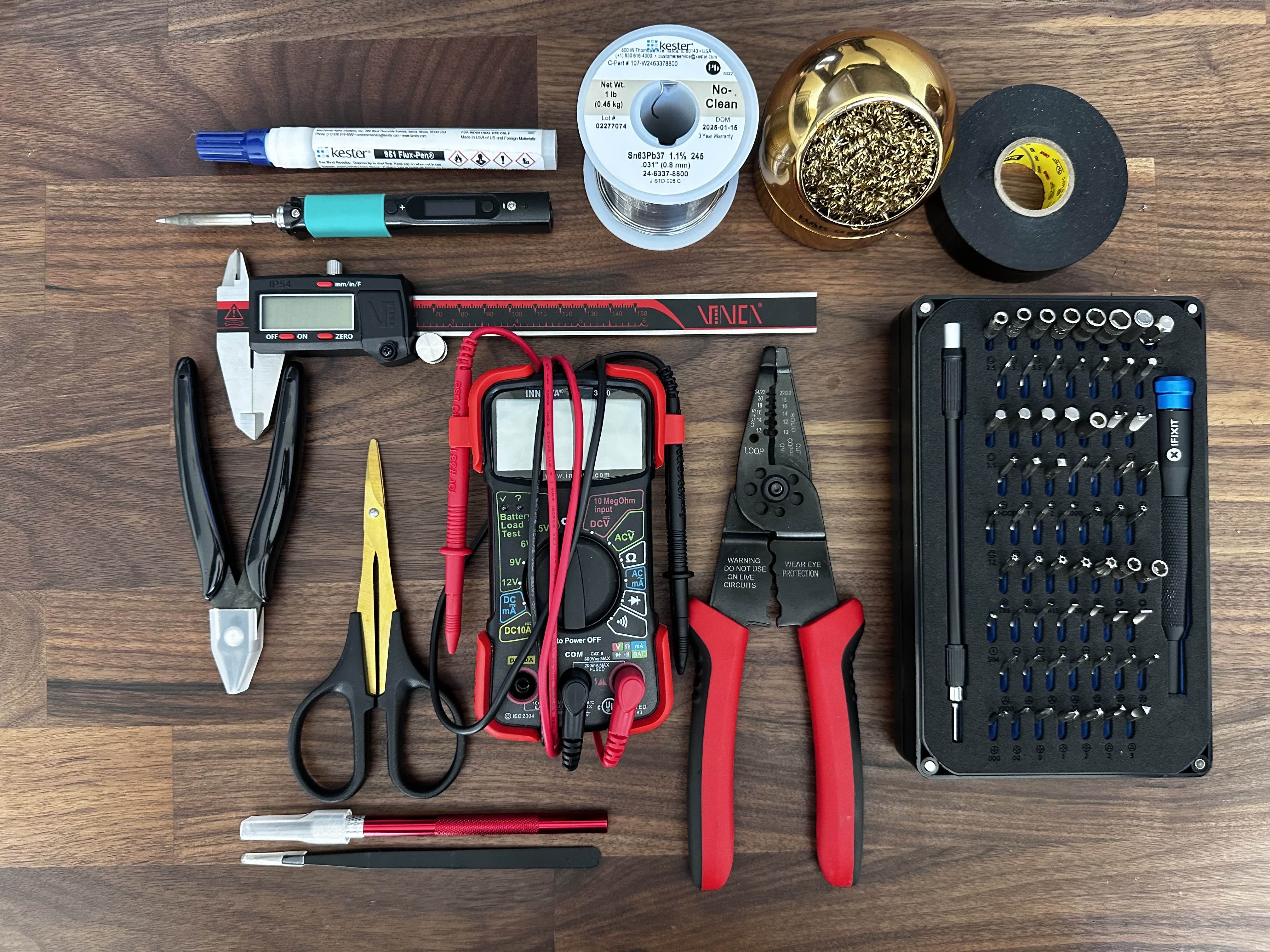
The full workstation setup. Everything has a spot, and being able to reach for any tool without searching made the build process much smoother. The practice PCBs visible in the background are what I used to get comfortable with the iron before touching any real components.
Parts List
Picking parts for a first FPV build is overwhelming in a way that's hard to appreciate until you're in the middle of it. Every component interacts with every other component — the frame dictates what size motors you can run, the motors determine what ESC current rating you need, the battery cell count affects motor KV selection, the video system has weight and mounting implications for the frame choice, and so on. There's no single "right" answer, which is part of what makes it hard to commit. After going through more spreadsheet revisions than I'm willing to admit, here's where I landed and why.
Frame
Volador II VD5 O4 Deadcat FPV T700 Frame
The deadcat geometry was the main selling point — the forward-angled front arms keep props out of the camera's view, which matters for recording clean footage. T700 carbon fiber is a step above the standard T300 used in cheaper frames, and the machining quality turned out to be excellent. The catch was that it was so new when I ordered it that it hadn't actually shipped yet. I waited over a month for this frame while all my other parts sat in boxes.
View Product →Motors
iFlight XING2 2207 1855KV (4x)
2207 stator size is the standard for 5-inch builds — enough torque to swing larger props without being unnecessarily heavy. 1855KV is a middle-ground rating for 6S batteries that gives decent efficiency at cruise and enough headroom for aggressive flying. iFlight has a strong reputation in the hobby and the XING2 line has been around long enough that most of the kinks have been worked out.
View Product →Flight Controller/ESC Stack
SpeedyBee F405 V4 55A BLHeli_32 4-in-1 ESC
Going with an integrated stack instead of separate FC and ESC boards was an easy call for a first build. Fewer solder connections means fewer opportunities to make mistakes, and the ribbon cable between boards eliminates a bunch of individual wires. The F405 processor runs Betaflight without issues, and 55A continuous on the ESC side is more than enough headroom for my motor and prop combination.
View Product →Video System
DJI O4 Air Unit Pro
This component was the reason I started the whole build. I wanted sharp, interference-free video without dealing with analog noise and static, and I wanted 4K recording built into the system so I wouldn't need a separate action camera adding weight. The O4 Pro delivers on both fronts. It's the most expensive single component in the build, but the video quality and reliability have been worth it.
View Product →Goggles
DJI Goggles N3
Once you commit to the DJI video ecosystem, you need DJI goggles to receive the signal. The N3s pair seamlessly with the O4 Pro, and the image quality through the lenses is sharp and bright. Coming from watching FPV footage on a phone screen, putting these on for the first time was a completely different experience — the immersion makes analog video look like watching a broadcast through static.
View Product →RC Receiver
RadioMaster RP3 ExpressLRS 2.4GHz
ExpressLRS (ELRS) is an open-source radio protocol that has taken over the FPV hobby for good reason. The latency is incredibly low, the range exceeds what you'd ever need for visual-line-of-sight flying, and the hardware is inexpensive. The RP3 is a tiny receiver that packs all of that performance into a package smaller than a postage stamp.
View Product →Battery
CNHL Speedy Pizza 1350mAh 6S Lipo 22.2V 150C
6S (22.2V) gives you more voltage headroom than 4S, which means the motors don't have to draw as much current for the same power output. 1350mAh is a compromise between capacity and weight — heavier batteries give longer flights but make the quad feel sluggish and stress the frame more on impacts. Also, I'll be honest, the name "Speedy Pizza" is just objectively great branding.
View Product →Propellers
Gemfan Hurricane 51466 V2
The Hurricanes are a well-established prop in the 5-inch FPV world. The tri-blade design offers a good balance of thrust and efficiency — aggressive enough for freestyle, smooth enough for cruising. Props are consumables in this hobby (you will break them), so I bought several sets. They've held up well so far and I haven't felt the need to try anything else yet.
View Product →Lost Model Buzzer
VIFLY Finder 2
This is a self-powered buzzer that screams when the drone loses power or you trigger it from your transmitter. It's a few grams and a few dollars, and it has already saved me from losing the entire quad in tall grass. When a dark carbon fiber drone goes down in vegetation, you are not finding it by eyesight alone. Buy one of these.
View Product →Capacitor
470uF 50V (downsized from original 1000uF)
Capacitors smooth out the voltage spikes that happen when motors change speed rapidly. I originally ordered 1000uF caps based on a forum recommendation and they turned out to be comically oversized for the frame. Measuring the actual available space would have saved me a week of waiting for the smaller replacements to arrive. Lesson learned.
View Product →General Approach to Component Selection
My philosophy was "buy once, cry once" for anything structural or electrical. I'd rather spend more upfront on a component with a proven track record than save twenty dollars and risk a failure that could damage other parts (or the drone itself) in a crash. The one exception is propellers — those are designed to be broken and replaced, so there's no reason to spend extra on premium props when you're still learning and crashing regularly.
Week 1: Research & Planning
I expected the research phase to last a few days. What I didn't account for is that every answer in this hobby leads to three more questions, and every forum post you read will contradict the last one you just finished. The FPV community has strong opinions about everything — motor brands, frame geometry, radio protocols, prop pitch — and as a newcomer, it's nearly impossible to tell which opinions are based on experience and which are just brand loyalty. I spent the better part of three weeks reading, watching, comparing, and revising my parts list before I felt confident enough to actually order anything.
How the Research Actually Went
In hindsight, the research followed a pretty predictable arc from optimism through confusion to eventual decision fatigue. Here's the breakdown:
Day 1–3: The Optimism Phase
Watched two or three build videos on YouTube, thought "that doesn't look too bad," and started a rough parts list in Google Sheets. My initial budget estimate was around $400 and I figured I could have the whole thing done in a weekend. In retrospect, this level of confidence was completely unjustified but I suppose everyone starts somewhere.
Day 4–7: The Complexity Reveal
Started actually reading the specs on components and quickly realized that nothing exists in isolation. Your frame size constrains your motor options, your motor KV interacts with your battery voltage to determine RPM, your prop pitch and diameter affect how much current the motors draw, and your ESC needs to handle that current with headroom to spare. Every time I locked in one component, it changed the requirements for two others. I was on parts list revision four by the end of this stretch, and I'd begun to understand why people spend weeks just on research.
Day 8–14: The Deep Dive
This is when I went from casual interest to genuine obsession. I learned about deadcat vs. X-frame layouts and why the front arm geometry matters for camera footage. I read deep-dives on analog vs. digital video systems and came away convinced that DJI's digital was worth the premium for a first build. I discovered ExpressLRS and spent three full days reading about radio protocols, comparing ELRS latency numbers to Crossfire and TBS, and watching range test videos. I understood about half of what I was reading, but enough stuck that I could make informed decisions. Parts list revision twelve.
Day 15–21: Decision Fatigue
At some point the research stops being productive and starts being procrastination. I spent an entire evening going back and forth between 1855KV and 1900KV motors — a difference that, in practice, I would never notice as a beginner pilot. I eventually realized I was overthinking it and forced myself to just commit. Any modern, well-reviewed set of components that are compatible with each other will work well enough for someone who's never flown before. The experience of building and flying teaches you more than any amount of spreadsheet optimization.
How I Chose Each Major Component
Frame: Volador II VD5
I'm going to be honest — I saw this frame in a build video and thought it looked cool. The deadcat arm layout stood out from the standard X-frames, and I liked that it was designed specifically with DJI O4 compatibility in mind. The T700 carbon fiber specification was a nice bonus (it's stronger and stiffer than the more common T300), and the reviews from early buyers were positive. The fact that it was brand new and hadn't shipped yet when I placed my order turned out to be a significant complication, but as a product choice, it was the right call.
The Shipping Problem
What the product listing didn't make clear was that this frame was essentially a pre-order. It hadn't been manufactured yet when I placed my order. I ended up waiting over a month for it to ship while all my other components sat in boxes on my desk. If you're ordering a newly released frame from a smaller manufacturer, pay close attention to whether "in stock" actually means in stock.
Motors: XING2 2207 1855KV
iFlight's XING line has been a staple of the FPV community for several years, which means there's a large body of real-world data on reliability and performance. 2207 is the standard stator size for 5-inch quads — enough torque to handle aggressive flying without being unnecessarily heavy. I went with 1855KV because it's a sensible middle ground for 6S: efficient enough at lower throttle for decent flight times, but still capable of pulling hard when you want it to. I could have spent another week agonizing over alternatives, but at some point you just have to pick something and fly.
FC/ESC: SpeedyBee F405 V4
The decision between a combo stack and separate FC/ESC boards was straightforward for a first build. A stack means a single ribbon cable connects the two boards instead of individual wires for every signal and power connection. That's fewer solder joints, fewer chances for wiring mistakes, and a cleaner installation. SpeedyBee's documentation is better than average for the FPV industry, the F405 processor is well-supported by Betaflight, and 55A continuous on the ESC side provides plenty of headroom for my setup. The value proposition was clear.
Video System: DJI O4 Air Unit Pro
This was the component the entire build was designed around. I wanted crystal-clear digital video transmission without the noise and interference issues inherent to analog, and I wanted 4K onboard recording so I wouldn't need to mount a separate action camera. The O4 Pro was DJI's newest air unit at the time, which made it the best choice for longevity — DJI has a pattern of supporting their latest hardware for longer than previous generations. It's expensive, but having a reliable HD video feed with virtually zero latency and integrated recording has proven to be worth the investment.
What I Learned from the Research Phase
The most important takeaway from three weeks of research was that "good enough" is more than sufficient for a first build. I could have kept optimizing on paper indefinitely, but the marginal gains from choosing the theoretically perfect motor over a very good motor are completely invisible to a beginner pilot. The real learning starts when you build the thing and fly it. Research enough to make informed choices, then commit and move forward.
Week 2: Purchasing & Waiting
With my parts list finally locked in, I moved to the purchasing phase. My plan was simple and, as it turned out, optimistic: order everything at once, have it all arrive within a week or two, and start building. The FPV hobby had different plans. Components come from different vendors with different shipping timelines, and there's always at least one critical item that's either backordered, coming from overseas, or — in my case — not yet manufactured. The purchasing phase ended up being more of a patience exercise than a shopping spree.
The Ordering Process
I spread orders across several vendors based on price and availability. Here's how each category played out:
Electronics First
The FC stack, motors, and receiver were my first orders since they seemed like standard items with reliable availability. Amazon Prime had conditioned me to expect two-day shipping on everything, which turned out to be a poor baseline expectation for FPV components. The SpeedyBee stack arrived in three days (the one thing that actually met my expectations), the motors took about a week from a third-party Amazon seller, and the ELRS receiver got lost in USPS limbo for two weeks before showing up randomly in my mailbox with no tracking updates to explain the delay.
Tools and Consumables
Solder, flux, wire, heat shrink, zip ties, and all the small items you don't think about until you need them. These trickled in over about two weeks, which was actually fine because it gave me time to practice soldering on some cheap PCB kits before the real components arrived. I went through two full practice boards getting my technique consistent, and that turned out to be one of the best uses of the waiting time.
The DJI Ecosystem
The O4 Air Unit Pro and Goggles N3 were both in stock from major retailers and shipped within a few days. Say what you will about DJI's pricing, but their supply chain and logistics are on another level compared to smaller hobby companies. Having the goggles in hand early was actually helpful — I was able to update their firmware and get familiar with the DJI interface while waiting for everything else to arrive.
The Frame Situation
I ordered the Volador VD5 directly from Flyfish RC's website and only realized after the fact that it was essentially a pre-order. The product page showed it as available, but my order confirmation email had a vaguely worded note about "processing time." Over the following month, I checked my email daily for shipping updates, sent two polite inquiry emails (both answered with "soon"), and gradually came to terms with the fact that my build timeline was completely at the mercy of a factory I had no communication channel with.
Timeline Reality
Total elapsed time from first order to having every component in hand: about six weeks. The frame was the bottleneck, but even the "in stock" items took longer than expected between various shipping carriers and vendor processing times. If you're planning an FPV build, add at least two weeks to whatever timeline you think is reasonable, and identify your longest-lead-time item early so you can order it first.
Making Use of the Downtime
Having most of my components but no frame to put them in was frustrating, but I tried to use the time productively rather than just refreshing tracking pages:
- Soldering Practice — I bought a couple of cheap PCB practice kits and went through them multiple times until I could make consistent, shiny joints on small pads. This turned out to be the single most valuable thing I did before the actual build. By the time I was soldering real motor wires, the physical motions were familiar and I could focus on placement instead of technique.
- Software Familiarization — Downloaded Betaflight Configurator, DJI Assistant 2, and the ExpressLRS Configurator. Spent time clicking through menus, reading documentation, and understanding what each setting does. When it came time to actually configure the quad, I already knew where to find things instead of fumbling through unfamiliar interfaces.
- Workspace Setup — Set up a dedicated area on my desk with a silicone soldering mat, good overhead lighting, and organized storage for all the small hardware and tools. Having a clean, well-lit workspace made every stage of the build easier and more enjoyable.
- Targeted Research — Instead of the broad "learn everything" approach from Week 1, I focused specifically on build videos using my exact components. Took notes on wire routing paths, solder pad locations, and configuration details specific to the SpeedyBee F405 and DJI O4 integration. This turned out to be much more useful than general-purpose build guides.
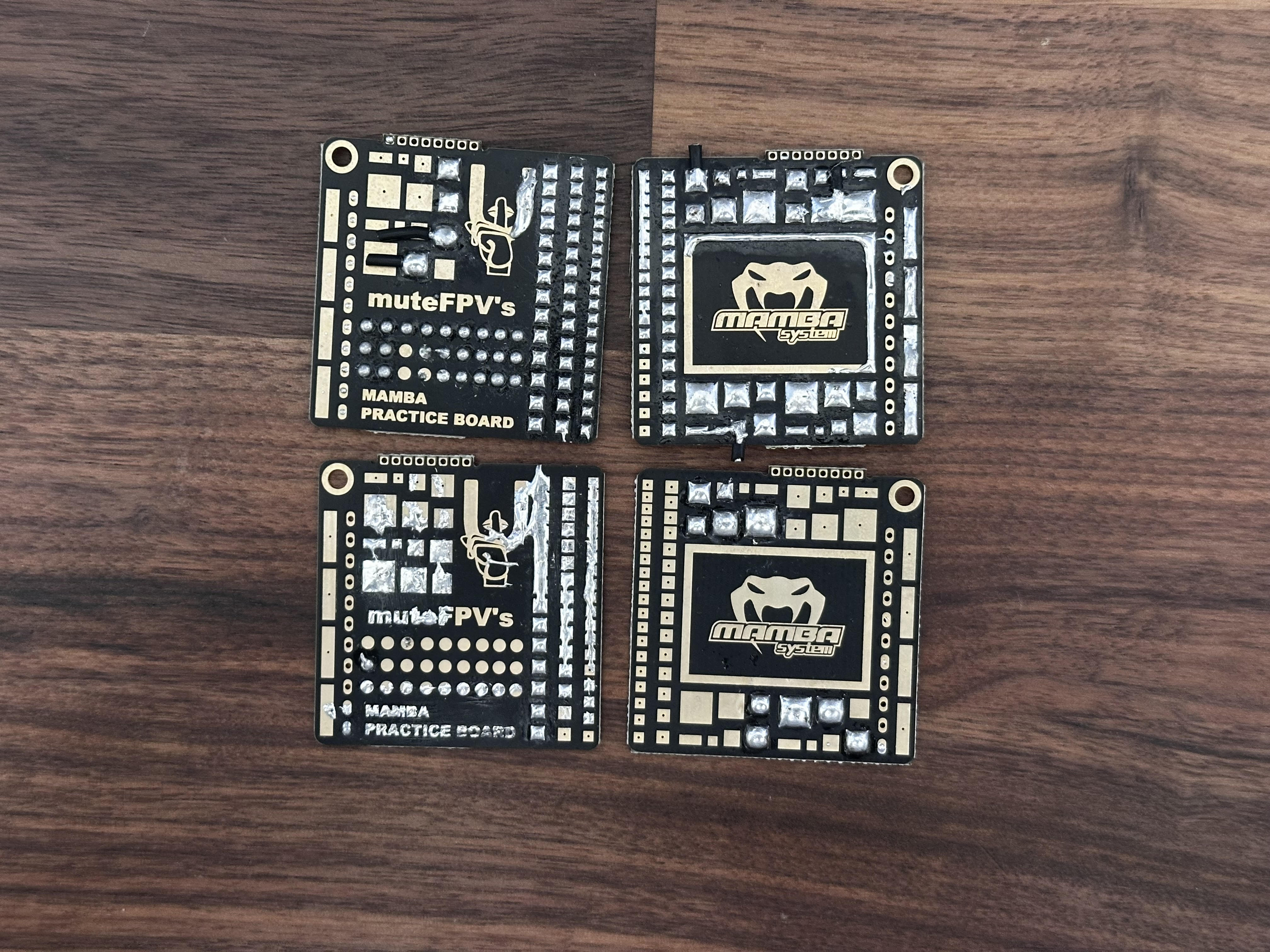
Practice PCBs from my soldering sessions. I went through several of these before touching any real components. The improvement from the first board to the last was significant.
Budget Update
My original back-of-napkin estimate was around $400 for the complete build. By the time I'd ordered everything — components, tools, consumables, and a few "while I'm ordering I might as well get..." additions — the actual total was approaching $1,080. Tools accounted for a significant chunk, but they're a one-time investment that carries over to future builds and other projects. The frame delay at least gave me time to come to terms with the real cost before more charges hit my card.
Week 3: Frame Arrival & Mechanical Assembly
Six weeks after I placed the order, the Volador II VD5 frame finally showed up at my door. I may have said something embarrassing out loud when I saw the box. After all that waiting, there was a brief moment of anxiety about opening it — what if something was missing or damaged? — but everything inside was perfect, and I could finally start the part of the project I'd been planning for months.
First Impressions of the Frame
The VD5 frame exceeded my expectations out of the box. The T700 carbon fiber has a clean matte finish that feels noticeably stiffer than the T300 frames I'd handled at a local meetup. The deadcat arm configuration gives the frame a distinctive profile — the front arms angle forward about 10 degrees, which pushes the front propellers out of the camera's field of view. The hardware bag was well-organized with labeled packets for different screw sizes, and the machining quality was excellent: clean-cut edges, properly drilled mounting holes, and no rough spots that needed sanding. For a small-batch frame from a relatively niche manufacturer, the fit and finish were impressive.
Workspace laid out and ready for assembly. After weeks of anticipation, having everything organized and within reach felt like preparing for surgery. The silicone mat and good lighting made more of a difference than I expected.
Frame Assembly
The VD5 ships partially assembled — the main plates and arm structure come pre-assembled, which saved time but also meant I didn't get to build the frame from completely bare components. The remaining assembly steps were straightforward but required attention to detail:
Bottom Plate & Battery Mount
The bottom plate serves as the battery tray and provides the mounting points for the FC/ESC stack standoffs. I applied a thin line of blue Loctite threadlocker to every screw during installation — it's a common recommendation in the FPV community because the vibration from running motors can slowly loosen hardware over time. The plate seated perfectly with proper clearance around all the mounting points.
FC Stack Standoffs
Installed four brass standoffs that create the mounting platform for the flight controller stack. The height of these standoffs determines the spacing between the ESC board and the FC board, so they need to be the right length to accommodate the ribbon cable connector. I measured the standoff height with calipers to confirm it matched the stack's specs before tightening anything down — getting this wrong would mean disassembling the entire stack later.
DJI O4 Mount Preparation
The frame includes dedicated mounting points for the DJI O4 Air Unit, including a camera cradle with tilt adjustment. I did a full dry fit at this stage — mounting the O4 unit temporarily to verify camera angle range, antenna routing clearance, and that nothing interfered with the FC stack position below. Everything aligned as expected, which was reassuring after the earlier delays.
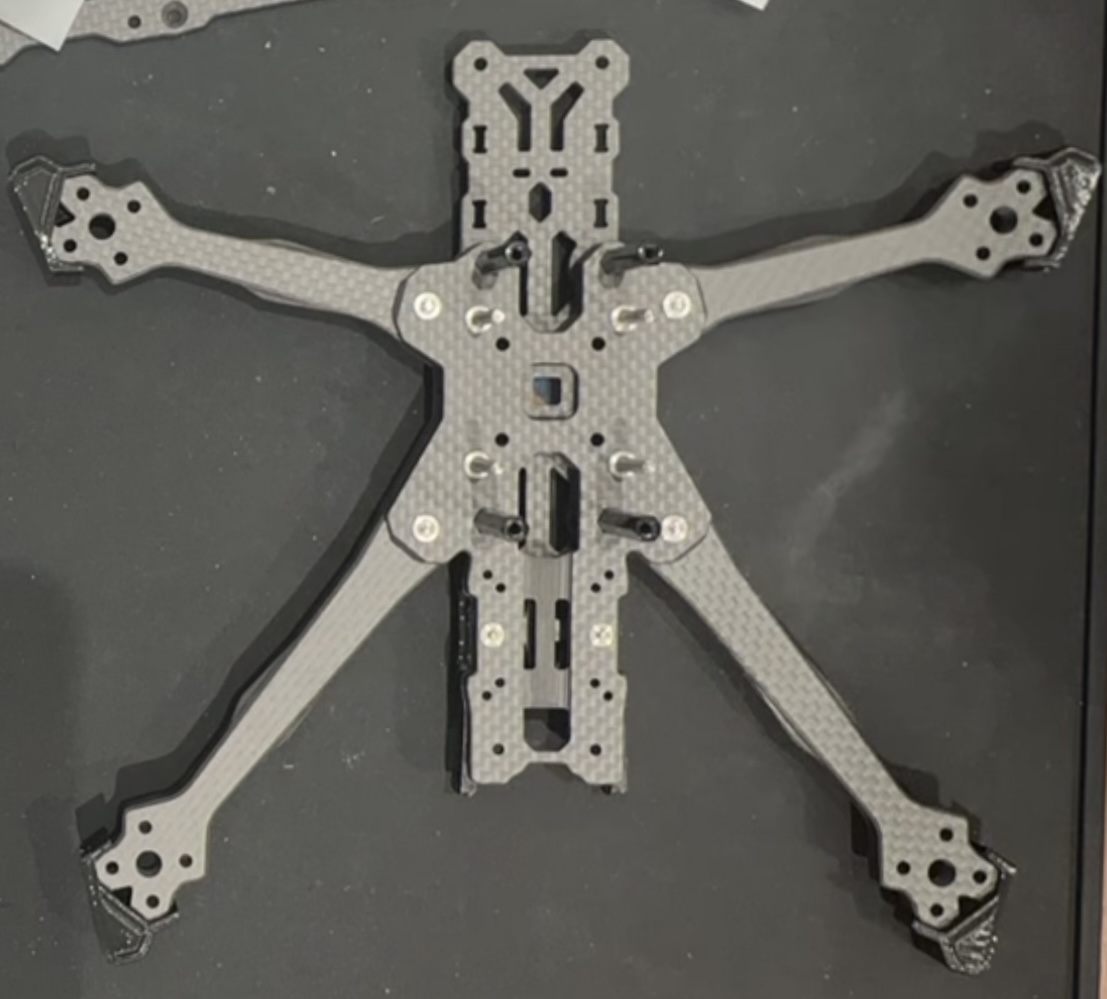
Frame fully assembled with standoffs, mounting hardware, and battery strap installed. The deadcat arm geometry is visible here — notice how the front arms angle forward compared to the rear arms.
Motor Installation
On paper, installing four motors is simple: four screws per motor, sixteen total. In practice, it requires careful attention to rotation direction, wire orientation, and screw length to avoid piercing the motor windings.
Motor Rotation Planning
FPV quads use a specific motor rotation pattern — typically "props-in" where adjacent motors spin in opposite directions and the overall pattern creates a stabilizing inward airflow. The deadcat layout adds a wrinkle because the frame isn't symmetric front-to-back, so I triple-checked the frame markings and Betaflight's motor diagram before committing. Getting even one motor direction wrong would result in an uncontrollable flip on the first throttle-up.
Wire Routing Strategy
Before tightening any motor down, I planned the wire path from each motor to the ESC board. The deadcat layout means the front motors are farther from the center than the rear motors, so the front wires need to be longer. I oriented each motor bell so that the wire exits faced toward the cleanest routing path to the frame's center, where the ESC solder pads would be. Planning this now saved significant headaches during the wiring phase later.
Threadlocker & Torque
Applied blue Loctite to every motor mounting screw. This is non-negotiable in FPV — the vibration from spinning props at 20,000+ RPM will work standard screws loose within a few flights if they're not locked. I also verified screw length with calipers before installation. Motor mounting screws that are too long can puncture through the arm and contact the stator windings inside the motor, which shorts the motor and can burn out the ESC. The included hardware was the correct length, but I measured anyway.
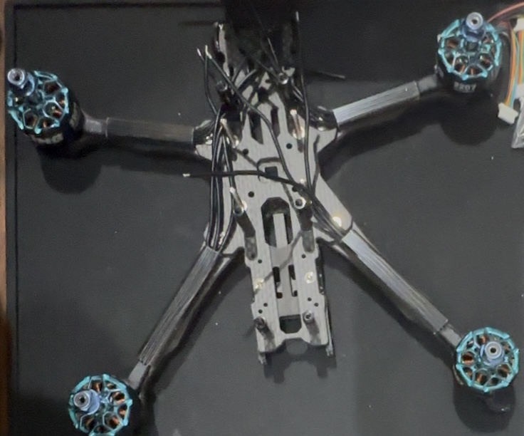
All four XING2 motors mounted and ready for wiring. The wire exit orientation on each motor is deliberate — each one faces toward the cleanest path back to the center of the frame where the ESC connections will be.
End of Week 3
Holding a partially assembled drone for the first time after months of planning and waiting was a genuinely great feeling. The mechanical assembly went smoothly with no surprises, everything fit as designed, and the frame with motors attached already looked like something that could fly. Ready for the electrical work next.
Week 4: ESC Wiring & The Capacitor Problem
This was supposed to be the week where I made clean solder joints, connected the power system, and moved on to final assembly. Instead, it became the week I learned why you should always measure the physical space available for a component before ordering it. The soldering itself went well — all that practice paid off — but a sizing mistake on the filter capacitors set me back by another week. Here's how it went.
Motor-to-ESC Connections
This was my first real soldering test on the actual build hardware. Practice boards are one thing; soldering wires to a $95 ESC board you can't easily replace is another. The stakes felt higher, but the technique was the same.
Wire Preparation
Cut all twelve motor wires to length with about 5mm extra for adjustment, then stripped exactly 3mm of insulation from each end using the automatic wire strippers. Pre-tinned every wire tip and every ESC pad with a thin layer of solder (using plenty of flux). Pre-tinning both surfaces is the key to fast, clean joints — when both sides already have solder on them, you only need to heat them together briefly to form the connection. I labeled every wire with masking tape to avoid mixing up motor positions.
The First Real Joint
I won't pretend I wasn't nervous for the first motor wire connection. Set the PINECIL to 350°C, touched the flux pen to the pad, held the pre-tinned wire against the pre-tinned pad, and applied the iron. The solder flowed together in about two seconds, forming a shiny concave joint. Clean, strong, and exactly what it was supposed to look like. All that practice with the cheap PCB kits directly translated to the real thing. The tension dropped noticeably after that first successful joint.
Finding a Rhythm
After the first few connections, the process became almost meditative. Flux the pad, position the wire, apply iron, remove iron, let cool, check joint. Repeat twelve times. I checked continuity with the multimeter after each motor (three wires per motor) to catch any shorts immediately rather than discovering them later when a battery was connected. All twelve joints came out clean with no rework needed.
Motor wires soldered to the ESC pads. Each joint was continuity-tested and checked for shorts immediately after completion. The wire routing follows the paths I planned during motor installation.
The Capacitor Sizing Mistake
This is where my lack of experience showed up in the most avoidable way possible. I'd ordered 1000uF 50V electrolytic capacitors based on a forum recommendation that basically said "bigger is better for filtering voltage spikes." What that recommendation didn't mention was that capacitor physical size scales with capacitance and voltage rating, and 1000uF 50V capacitors are... not small.
The Moment of Realization
I held the capacitor up to the frame's power distribution area and it was immediately, obviously wrong. The cap was roughly the size of a AA battery. The space available in the frame was maybe a third of that. It was like trying to fit a water bottle into a shot glass. A completely avoidable problem that a 30-second measurement with the calipers would have prevented.
Assessing the Problem
Pulled out the calipers and measured the available space: approximately 16mm maximum height and 10mm maximum diameter. My 1000uF caps measured 25mm tall and 12.5mm in diameter. Not even close. No amount of creative positioning or trimming was going to make these work. I needed different capacitors.
Finding the Right Size
Ordered 470uF 50V capacitors with smaller physical dimensions. 470uF is still plenty of capacitance for voltage spike filtering on a 5-inch quad — the 1000uF recommendation was overkill anyway, which is common in forum advice where people recommend what worked on their specific (often larger) frame without considering that dimensions vary. The new caps were projected to arrive in about a week, adding yet another delay to the build.
Fitting the Replacement Caps
Even the smaller 470uF caps were a tight fit in the frame's designated area. I ended up carefully trimming the outer plastic sleeve with a razor blade to shave a millimeter or two off the diameter so they'd seat properly. Not the most elegant solution, but the electrical function wasn't compromised — the plastic sleeve is just cosmetic protection over the aluminum can. The caps fit snugly after trimming and I could proceed with the power wiring.
The 470uF capacitor after trimming the plastic sleeve to fit the frame's power distribution area. Functional and secure, if not pretty.
Power Distribution Wiring
With the capacitor situation resolved, I moved on to the main power connections. These carry the full battery current, so joint quality is critical — a bad solder joint on a power pad creates resistance, which generates heat, which can melt insulation or damage the board.
Battery Lead Preparation
Used 12AWG silicone wire for the main battery connection. This gauge is oversized for the current draw of this particular build, but running heavier wire on the main power leads has essentially zero weight penalty and provides a safety margin. Soldered an XT60 connector to the wire ends with careful attention to polarity — red to positive, black to negative, verified with the multimeter before proceeding. Reversing polarity on the battery connector would be catastrophic for every component in the system.
ESC Power Connections
Soldered the battery leads to the ESC's main power input pads. These pads are larger than the signal pads and require more heat and more solder to fill properly. I used a higher iron temperature (380°C) for these joints and held the iron longer to ensure the solder flowed fully around the wire strands. Tested each joint for continuity and checked for shorts between the positive and negative rails immediately after.
Capacitor Installation
Soldered the trimmed 470uF capacitor across the main power rails, paying close attention to polarity markings on the cap. Electrolytic capacitors are polarized — connecting them backwards doesn't just fail to work, it can cause the capacitor to physically rupture, which is as dramatic and unpleasant as it sounds. The negative stripe on the cap body faces the ground rail. Verified with multimeter, secured with a small piece of electrical tape for vibration resistance.
Power System Complete
Despite the capacitor setback, the electrical work came together well once I had the right parts. All connections tested clean, no shorts detected between any power and ground points, and everything fit within the frame's constraints. The capacitor delay was annoying but ultimately a minor bump — and a lesson I won't need to learn twice.
Week 5: Final Assembly & Configuration
At this point, the frame was built, motors were mounted, and the power system was wired. What remained was installing the "brains" of the drone — the DJI video system, the ELRS receiver, and all the signal wiring that connects everything to the flight controller — plus the full software configuration in Betaflight and DJI's systems. This was the stage where the pile of parts would either become a functioning aircraft or an expensive cautionary tale.
DJI O4 Air Unit Pro Installation
The entire build was designed around this component, so getting the installation right was critical.
Vibration Isolation & Mounting
The VD5 frame has dedicated mounting points for the O4 Pro, but I added soft rubber dampeners between the unit and the frame anyway. Vibration transfers directly to the camera sensor, and even small amounts of motor vibration can show up as jello in the recorded footage. The dampeners add a couple grams of weight but provide meaningful isolation that protects video quality. I torqued the mounting screws snug but not overtight — crushing the rubber dampeners defeats their purpose.
Cable Routing
The O4 Pro has several cables coming off it — the camera ribbon, two antenna leads, and the MSP data cable for flight controller communication. The frame has built-in channels and slots designed for cable routing, which kept everything organized and away from the prop arcs. Every cable got a small loop of slack secured with a zip tie to provide strain relief — a direct connection with no slack is one hard landing away from pulling loose.
Antenna Positioning
Positioned the two transmission antennas at roughly 90-degree angles to each other for optimal spatial diversity. This means that no matter what orientation the drone is in relative to the goggles, at least one antenna has a favorable radiation pattern. The frame has molded antenna tunnels that protect the coax cables while maintaining the correct exit angles. I was careful not to bend the coax too sharply — kinking a coax cable can damage the internal conductor and degrade signal quality.
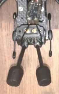
DJI O4 Air Unit Pro installed with vibration dampeners and all cables routed through the frame channels. The camera has full tilt adjustment range for different flying styles.
Custom 3D-Printed ELRS Receiver Mount
The frame didn't include a specific mounting point for the ExpressLRS receiver, which created an opportunity to put my 3D printer to practical use. The receiver needed to be positioned away from carbon fiber (which attenuates radio signals) and away from other electronics (which can generate interference), with the antenna extending into clear air.
Design in Fusion 360
Measured the RP3 receiver dimensions with calipers (it's tiny — roughly 12mm x 12mm x 3mm) and modeled a bracket in Fusion 360. The design criteria were simple: hold the receiver securely, position it on top of the frame stack where it would have minimal carbon fiber shielding between it and the sky, and include a slot for the antenna wire to exit cleanly. I kept the geometry straightforward since this was functional, not decorative.
TPU Printing
Printed the mount in TPU (thermoplastic polyurethane), which is a flexible filament with good vibration-dampening properties. TPU is significantly harder to print than PLA — it's soft and tends to jam in Bowden-tube setups — but the flexibility means the mount absorbs impacts rather than cracking, and the vibration isolation helps keep the receiver's gyro data (used by ELRS for telemetry) clean. Took three print iterations to get the fit dialed in, mostly tweaking tolerances for a snug press-fit.
Installation
The finished mount press-fit onto the top standoff of the FC stack and positioned the receiver with its antenna extending vertically into clear space above the frame. Signal testing confirmed strong RSSI values in all orientations, validating the placement choice. This was one of those satisfying moments where having a 3D printer turned a missing-part problem into a 30-minute design-and-print solution.
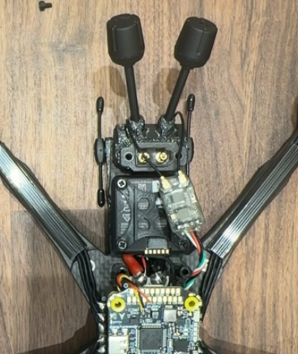
The custom TPU mount holding the RadioMaster RP3 receiver above the frame's carbon fiber. The flexible material absorbs vibration and the elevated position gives the antenna a clear path to the transmitter.
Signal Wiring Connections
With the major components mounted, it was time to connect everything to the flight controller's signal pads. These are small, close together, and carry data rather than power — so the wire gauge is finer and the joints need to be precise.
ELRS Receiver to FC
Soldered the RP3 receiver to UART6 on the SpeedyBee F405 (TX6 and RX6 pads, plus 5V power and ground). Used 30AWG silicone wire for the signal connections — thin enough to be lightweight and flexible, but still easy to work with. Applied flux to both the wire tips and the pads, and made quick joints to minimize heat exposure to the FC board. Long dwells with the iron on a PCB pad can delaminate the copper trace from the board, so speed matters here.
Buzzer Connection
Connected the VIFLY Finder 2 to the dedicated buzzer pads on the FC. This self-powered buzzer activates when it loses power (i.e., when the battery disconnects in a crash) or when triggered manually from the transmitter. It weighs almost nothing and has already justified its existence by helping me locate the drone in a field after a disorientation crash. Genuinely essential equipment.
DJI MSP Link
Wired the O4 Pro's data cable to UART1 for MSP (MultiWii Serial Protocol) communication. This allows the flight controller to pass telemetry data — battery voltage, current draw, GPS coordinates, flight mode — to the DJI goggles, where it appears as an on-screen display overlaid on the video feed. Essential for monitoring the drone's status during flight without taking your eyes off the video.
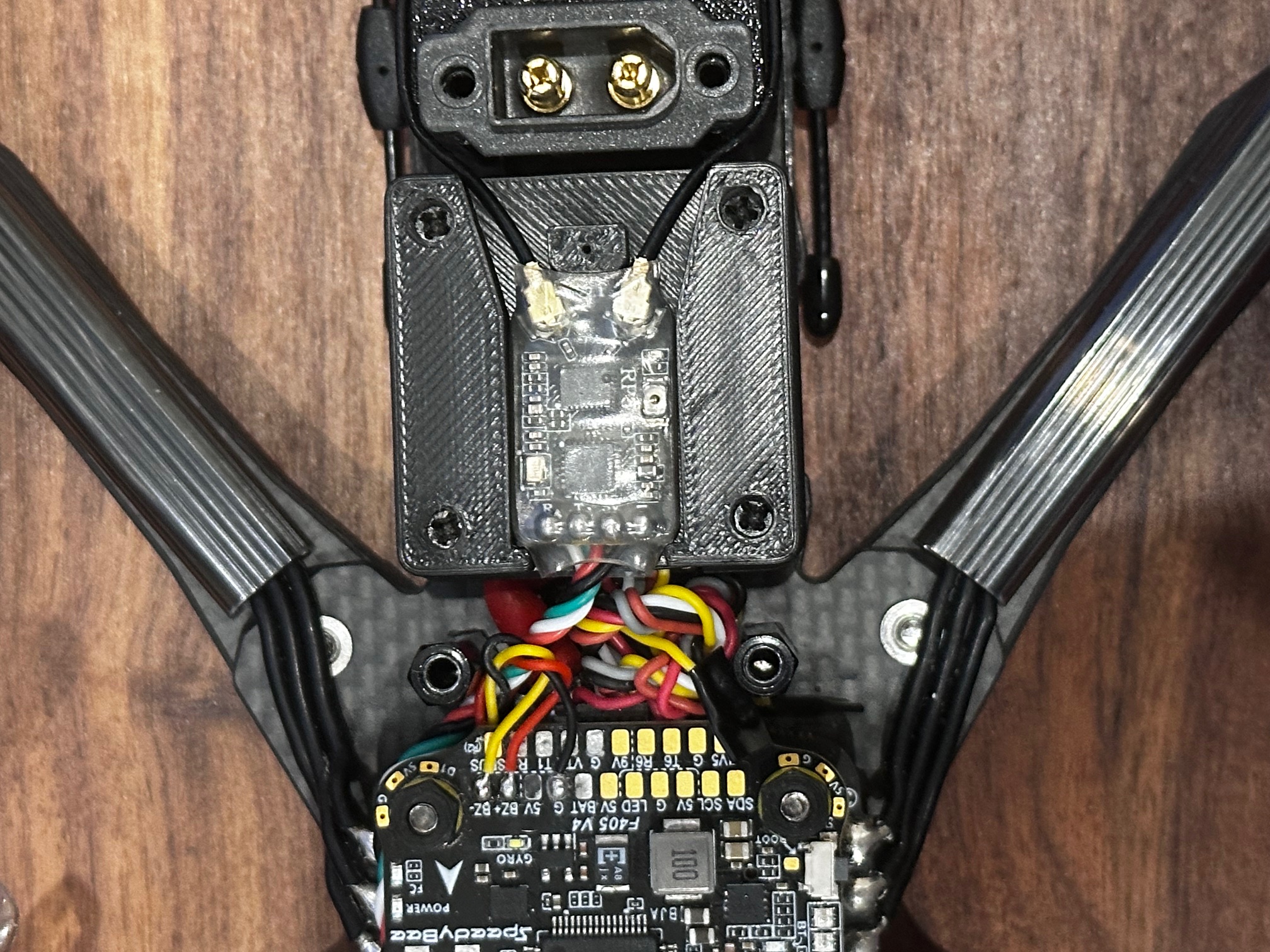
All signal wiring completed on the flight controller board. Clean joints and proper wire management reduce the chance of issues during operation.
Stack Assembly & Closure
The SpeedyBee stack uses a ribbon cable to connect the FC and ESC boards. Conceptually simple, but proper alignment is important because the connector is fragile.
Ribbon Cable Connection
Carefully aligned the ribbon connector pins and pressed firmly until the latch clicked. This cable carries power, ground, and all the signal connections between the two boards, so a loose or misaligned connection would cause intermittent failures that would be difficult to diagnose in flight. I verified the connection by gently tugging the cable — it should resist without the latch releasing.
Stack Mounting & Isolation
Installed the assembled stack onto the brass standoffs in the frame, with a thin layer of foam padding between the stack and the top plate. The foam serves as additional vibration isolation for the FC's gyroscope — the gyro measures the drone's rotation rate thousands of times per second, and any mechanical vibration that reaches it shows up as noise in the flight control loop, which degrades flight performance and can cause oscillations.
Final Physical Assembly
With all electrical work complete, the remaining tasks were wire management and final inspection.
Wire Management
Secured every loose wire with zip ties and small strips of electrical tape. Every connection got strain relief — a small loop of slack secured near the solder joint so that any tension on the wire loads the zip tie, not the solder joint. Trimmed all zip tie tails flush with the flush-cut snips. Vibration and impacts will test every connection over time, so strain relief isn't optional on an FPV quad.
Full Electrical Inspection
Went through the entire build with the multimeter one more time. Checked for shorts between power and ground on the main bus, confirmed continuity on every motor connection and signal wire, and verified that no exposed conductors were touching the carbon fiber frame (which is electrically conductive). Probably overly paranoid for a first power-up, but I preferred spending thirty minutes with the meter over potentially releasing the magic smoke from a wiring error.

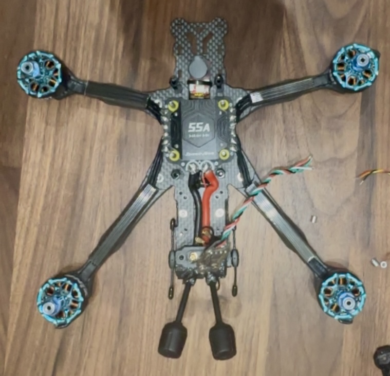
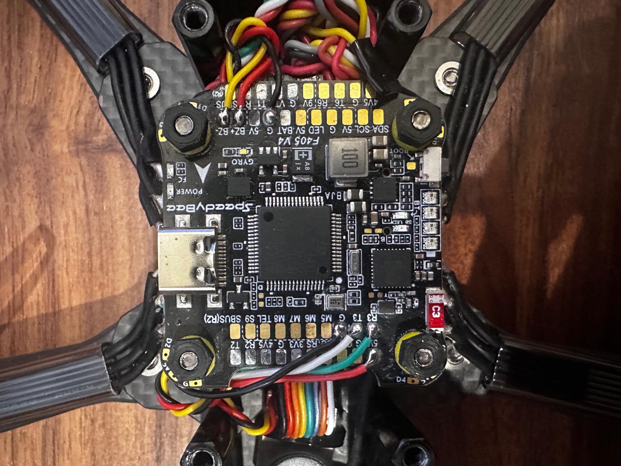
The completed physical build with all components installed, wired, and secured. Every connection has been tested and every wire is strain-relieved.
Betaflight Configuration
Hardware done, but a drone without proper firmware configuration is just an expensive desk ornament. Betaflight is the open-source flight controller firmware that runs on the SpeedyBee F405 and handles everything from interpreting stick inputs to PID control of the motors.
Firmware Flash
Updated the FC to Betaflight 4.5.1 through the Betaflight Configurator Chrome app. Always use the latest stable release for new builds — it includes the most recent bug fixes and performance improvements. The flash process was straightforward: connect via USB, select the correct board target (SPEEDYBEEF405V4), and click flash. Took about 30 seconds, though I held my breath the entire time.
UART / Port Configuration
Configured UART1 for MSP (DJI communication) and UART6 for CRSF (the protocol ExpressLRS uses). Also enabled the buzzer output and verified the LED strip port was available for future use. Incorrect UART assignment is one of the most common sources of "nothing works" confusion in FPV builds, so I double-checked each setting against the SpeedyBee wiring diagram.
Receiver Binding & Verification
Set the receiver protocol to CRSF in Betaflight, then bound the RP3 receiver to my transmitter using the ExpressLRS binding procedure. Verified all four stick channels (throttle, roll, pitch, yaw) were mapped correctly and responding with full range. Also confirmed that the aux channels for arming, flight mode switching, and buzzer activation were working as expected.
Motor Protocol & Direction
Set motor protocol to DSHOT600 — a digital protocol that's faster, more reliable, and more precise than older PWM methods. Used Betaflight's motor test tab to spin each motor individually (without props!) and verified the rotation direction matched the frame's required pattern. Two motors needed direction reversal, which I did through the BLHeli_32 configurator with a few clicks. Getting motor direction wrong results in an immediate, violent flip on first throttle-up.
Flight Mode Setup
Configured three flight modes accessible via a switch on the transmitter: Angle mode (auto-levels when sticks are centered — the safest for learning), Horizon mode (auto-levels but allows flips at full stick deflection — a stepping stone), and Acro mode (no auto-leveling, full manual control — the eventual goal). Set up the arm switch, buzzer activation switch, and a kill switch for emergencies. Conservative starting configuration for a first-time pilot.
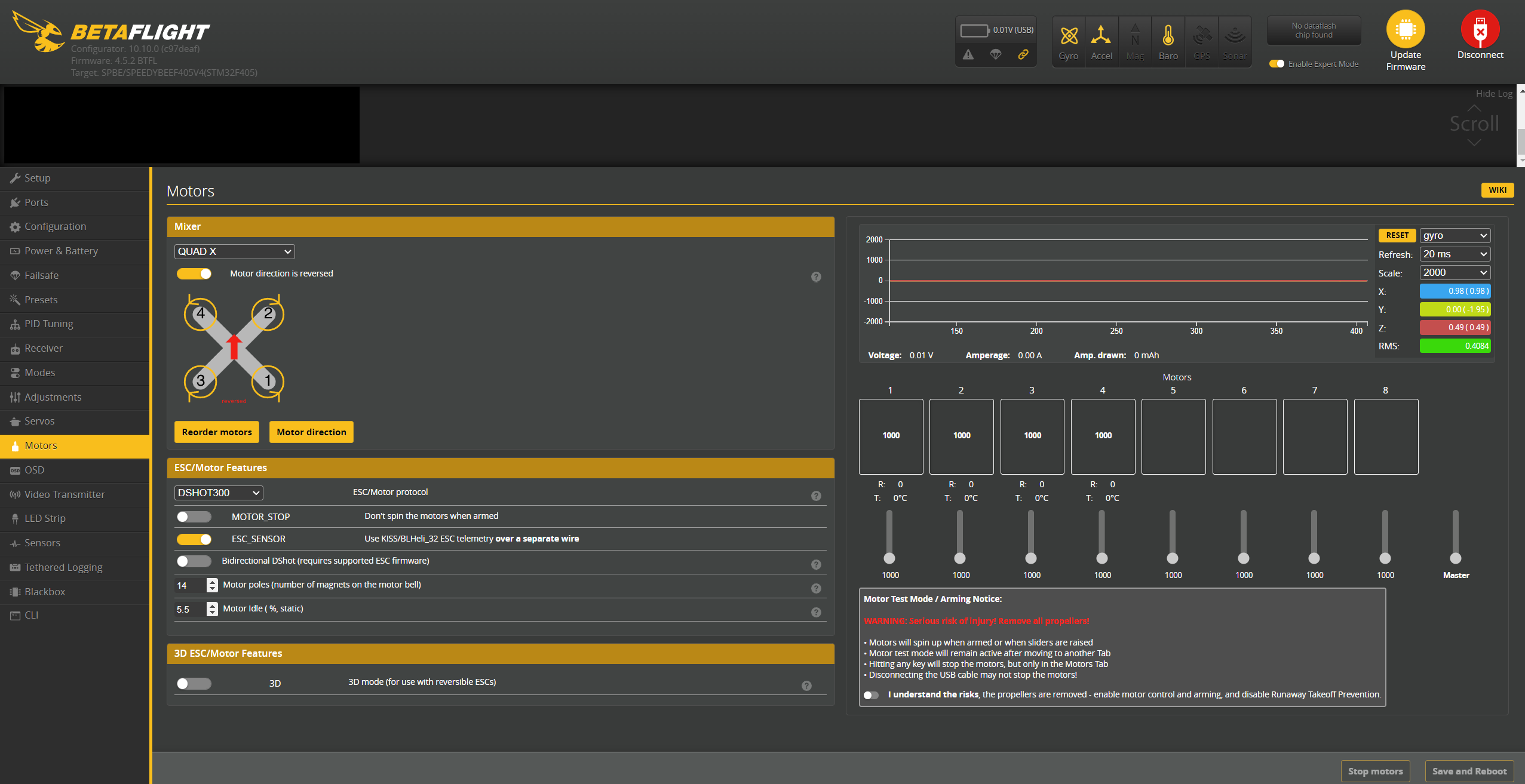
Betaflight's motor testing interface — used to verify each motor spins in the correct direction before props go on.
DJI System Configuration
Getting the DJI video system talking to the flight controller and goggles required its own configuration workflow, separate from Betaflight.
Goggles Pairing
Paired the Goggles N3 with the O4 Air Unit Pro through the DJI Fly app on my phone. The process was surprisingly painless — DJI's ecosystem integration is one of their genuine strengths. Both devices found each other immediately and the pairing completed in under a minute. The moment live video appeared in the goggles from a camera I'd wired and mounted myself was one of the highlights of the entire build.
OSD (On-Screen Display) Configuration
Configured the OSD elements in Betaflight to overlay critical flight data on the video feed: battery voltage (to know when to land), flight timer, GPS coordinates, RSSI (signal strength), and current draw. This information appears both in the live goggle feed and gets burned into the 4K recording, which is useful for reviewing flights afterwards and diagnosing any issues.
Camera & Recording Settings
Dialed in the O4 Pro's camera settings for my local flying conditions. Set recording to 4K at 30fps for the best resolution, adjusted white balance and exposure for outdoor daylight, and tweaked the color profile toward a flatter look that gives more flexibility in post-processing. The image quality even before any color grading was noticeably better than what I'd seen from analog systems in comparison videos.
Range Testing
Tested both the control link (ELRS) and video link (DJI) range before committing to a first flight. Walked to the end of my block with the drone powered on, monitoring RSSI in the goggles and the ELRS telemetry on my transmitter. Both links maintained solid, clean connections well beyond the distance where I could actually see the drone. The range capability of modern FPV systems far exceeds what you need for visual-line-of-sight flying, which is reassuring from a safety standpoint.
Build Complete
After weeks of building, wiring, configuring, and testing, everything was finally working together as a unified system. All connections solid, all software configured, all systems communicating correctly. The drone was ready for its first flight — and I was simultaneously excited and terrified.
Testing, Troubleshooting & First Flight
The build was complete and the software was configured, but there was a meaningful gap between "everything looks good on the bench" and "I'm confident enough to actually fly this thing." I ran through every pre-flight test I could think of — partly out of thoroughness, partly out of nervousness — before heading to a field for the moment of truth.
Pre-Flight Testing
The goal was to catch every possible problem on the ground, where the consequences are measured in time rather than in broken carbon fiber.
First Battery Connection
Connected a battery for the first time and waited. No smoke, no sparks, no concerning smells — just a clean power-up with the FC's status LED blinking the expected pattern and the correct voltage reading on the OSD. This was the single most nerve-wracking moment of the entire build. Everything after this felt manageable by comparison. Tested all flight controller functions, receiver inputs, and motor responses with props removed.
Motor Direction Final Check
Used Betaflight's motor test function to spin each motor individually and confirmed the rotation direction against the frame diagram one more time. I'd already verified this during configuration, but checking again with props off right before the first flight felt like basic due diligence. Wrong motor direction equals an instant uncontrollable flip, and that's the kind of mistake you only get to make once.
Control Link Range Test
Walked about 200 meters from the powered-on drone while monitoring RSSI values in the goggles. The ELRS link maintained a solid connection with signal strength barely dropping from the maximum. The video feed from the DJI system stayed crystal clear at the same distance. Both systems have far more range than I'll ever need within visual line of sight, which provides a comfortable safety margin.
Failsafe Verification
Configured and tested failsafe behavior: if the receiver loses the control signal, the flight controller immediately disarms the motors. Tested by powering off the transmitter with the drone armed on the ground — motors stopped within a fraction of a second. This is a non-negotiable safety feature. A drone that keeps flying when you lose control is a danger to people and property.
Preparing for First Flight
Found a large open field well away from people, vehicles, buildings, and anything expensive or breakable. First flights have a way of not going according to plan, and having plenty of empty space in every direction removes a lot of the risk.
Prop Installation
Installed the Gemfan Hurricane props, carefully matching the CW and CCW markings to the motor rotation pattern. Tightened prop nuts firmly but not aggressively — overtightening can crack the plastic prop hub, and the motor shaft's self-tightening design means the spinning motion keeps the nut secure anyway. Applied a small amount of threadlocker as additional insurance.
All-Up Weight
Weighed the fully loaded drone: 485 grams including the battery. Heavier than my initial estimate, mostly because the DJI O4 system adds significant mass compared to an analog setup. Still within a reasonable thrust-to-weight ratio for the motor and prop combination — the quad should have plenty of power margin even at this weight.
Flight Mode Selection
Set the flight mode switch to Angle mode for the first flight. Angle mode auto-levels the drone when you release the sticks and limits the maximum tilt angle, which makes it dramatically more forgiving for a nervous first-time pilot. Acro mode — full manual, no self-leveling — would wait until I had some hours of stick time and could trust my muscle memory.
First Flight
Standing alone in a field with the drone armed, goggles on, and nothing between me and a maiden flight except the throttle stick. No video, no forum post, no amount of simulator time fully prepares you for this moment. I took a breath and slowly pushed the throttle forward.
Initial Hover
The drone lifted off the ground cleanly and held position at about three feet. The flight controller was doing its job, smoothing out my shaky stick inputs into a stable hover. No wobbles, no oscillations, no drift — just a clean, steady hover with the motors humming evenly. The relief I felt in that moment was hard to describe. Months of planning, waiting, building, and configuring had all come down to this, and it worked.
Careful Maneuvering
Started with gentle forward/back and side-to-side movements. The drone responded predictably and smoothly to every input. The ELRS control link felt precise and immediate — zero perceptible lag between stick movement and drone response. The DJI video in the goggles was sharp and fluid, giving me a clear view of the surroundings. Confidence built quickly as I expanded the movement envelope, flying slow laps around the field.
Vibration Assessment
After landing, I checked the gyro data logs in Betaflight. The traces were clean with minimal high-frequency noise, indicating that the vibration isolation (rubber dampeners, foam padding, balanced props) was doing its job. Clean gyro data means the PID controller has accurate information to work with, which translates directly to smooth, predictable flight behavior.
Power System Under Load
Gradually increased throttle to test the power system at higher loads. Battery voltage remained stable under draw, no individual ESC was running notably warmer than the others, and the motor temperatures after landing were well within normal range. The 55A ESCs had plenty of current headroom for the loads this motor/prop combination was pulling.
First Flight: Success
Ten minutes of flying without a single crash. The drone flew exactly as intended — stable, responsive, and predictable. Every component choice and every careful solder joint and every hour of configuration work paid off in those ten minutes. The sense of accomplishment was immense — I'd gone from zero experience to flying a machine I built from individual components with my own hands.
Post-Flight Review
Brought the drone home, landed, and immediately started analyzing what went well and what needed adjustment.
Footage Review
Pulled the 4K footage from the O4 Pro's onboard storage and reviewed it on my monitor. Image quality was excellent — sharp, properly exposed, with accurate colors and good dynamic range. The electronic stabilization smoothed out most of the vibration that was invisible in the live feed but visible in the recorded file. Worth every dollar of the DJI premium.
Battery & Endurance
Flight time was about four minutes of gentle hovering and slow cruising before the low-voltage alarm triggered. The 1350mAh 6S pack provides good instantaneous power but limited total energy given the drone's 485g all-up weight. Four minutes is typical for this weight class and battery capacity — longer flights would require a larger (heavier) battery, which trades flight time for agility and crash durability.
Control Link Assessment
The ELRS control link was flawless. Zero dropouts, imperceptible latency, and a rock-solid connection throughout the entire flight. The telemetry data showed consistent signal strength with no concerning dips. The ExpressLRS hype is completely justified — it's a genuinely excellent control system, especially given how inexpensive the hardware is compared to alternatives.
Issues Found and Resolved
The first flight wasn't entirely problem-free. A few issues surfaced that needed attention:
Minor Video Vibration
Problem: Reviewing the 4K footage revealed subtle vibration artifacts during rapid throttle changes — visible as a slight "jello" effect on straight lines in the image.
Solution: Rebalanced all four props with a magnetic balancer (one was slightly heavier on one blade), retightened every motor mounting screw, and added an additional layer of foam dampening between the O4 unit and the frame mount. The vibration was significantly reduced on the next flight.
Uneven ESC Temperature
Problem: After extended hover testing, one ESC (motor 3) was running noticeably warmer to the touch than the other three.
Solution: Inspected the solder joints on motor 3's connections and found one slightly dull, grainy joint — a "cold joint" that was creating extra resistance and generating heat. Reflowed the connection with fresh flux, producing a clean shiny joint. Temperature equalized with the other ESCs on subsequent flights.
Slow GPS Acquisition
Problem: The O4 Pro's GPS was taking several minutes to acquire satellite lock, longer than expected.
Solution: The GPS antenna was partially shielded by other electronics and the carbon fiber top plate. Repositioned the O4 unit slightly to give the GPS antenna a clearer view of the sky. Lock time improved from several minutes to under a minute in subsequent flights.
Lessons from Early Flights
Start slow and conservative, then gradually expand your envelope. The drone is capable of far more than a beginner pilot can handle — which is exactly what you want. Better to have performance headroom you grow into than to outgrow your equipment in a month. Every flight is a learning opportunity, and the incremental improvement in stick skills is surprisingly fast once you start putting in hours.
Lessons Learned
Now that the build is done and I have some flights logged, here's an honest assessment of what this project taught me. Some of these lessons were predictable in hindsight, others caught me off guard.
What Worked Well
Investing in Research
Despite the analysis paralysis, the time I spent understanding component interactions paid off. Every major part I chose has performed well in practice, and I haven't had any "I wish I'd bought the other one" regrets. The research didn't just help with purchasing — it gave me enough background knowledge that I could troubleshoot problems intelligently instead of just guessing.
Buying Quality Tools
The PINECIL, the Kester solder and flux, the automatic wire strippers — every good tool made every task easier and produced better results. The difference between a $25 Amazon iron and a proper temperature-controlled soldering iron isn't marginal; it's transformative. Good tools pay for themselves in time saved and frustration avoided, and they last across multiple projects.
Practice Before Building
Going through multiple practice PCB kits before touching real components was one of the best decisions I made. By the time I was soldering $95 ESC boards and tiny receiver pads, the physical technique was already muscle memory. I could focus on placement accuracy and wire routing instead of worrying about whether my joints would hold. The investment was maybe $15 in practice kits and a few hours of time.
Documenting Everything
I took photos at every stage of the build, and it saved me multiple times. When I couldn't remember which UART I'd wired the receiver to, I had a photo. When I needed to reference a wire routing path after removing the top plate, I had a photo. When I wanted to build this documentation page, I had photos. Document your build — your future self will be grateful.
What I'd Do Differently
Measure Everything Before Ordering
The capacitor debacle was entirely preventable. If I'd checked the physical dimensions of the frame's cap mounting area before ordering, I would have bought the right size the first time and avoided a week of delay. This applies broadly: never assume a component will fit. Measure the space, check the datasheet dimensions, and verify compatibility before your money leaves your wallet.
Order Spares for Small Hardware
I should have ordered extra motor screws, standoff hardware, zip ties, and XT60 connectors from the start. Small parts get dropped, lost, stripped, or damaged during a build, and waiting three days for a $2 bag of screws to arrive is maddening when it's the only thing holding up the entire project. Buy extras of anything that's cheap and consumable.
Set Realistic Timelines
My original "build it in a weekend" estimate was wildly optimistic. Between shipping delays, the frame backorder, the capacitor re-order, and the natural pace of learning new skills, the project took closer to two months from first order to first flight. If I'd set that expectation from the beginning, the delays would have felt less frustrating. This hobby operates at its own pace.
Consider Starting with Analog Video
This might be controversial, but for a pure first-build-and-learn-to-fly experience, an analog video system would have been simpler, lighter, and cheaper. The DJI system is incredible and I don't regret it, but it adds weight, cost, and a layer of ecosystem complexity that isn't strictly necessary when you're just trying to learn the fundamentals. A stronger case could be made for starting analog and upgrading to digital once you know you're committed to the hobby.
Things I Didn't Expect
The Community
The FPV community turned out to be one of the best parts of the hobby. Reddit, Discord servers, and local Facebook groups were full of people who were genuinely happy to help a newcomer with technical questions, troubleshooting, and part recommendations. I expected gatekeeping and got the opposite — experienced pilots offering advice, lending tools, and inviting me to fly with them. Don't try to figure everything out alone.
Software Depth
I expected the hardware assembly to be the challenging part. The hardware was challenging, but Betaflight configuration has layers of depth that go far beyond basic setup. PID tuning, filter configuration, rate profiles, motor output limiting, RPM filtering — there's an entire world of software optimization that I've barely scratched the surface of. Default settings fly well, but the tuning rabbit hole is endless for those who want to pursue it.
The Build-More Instinct
Finishing one drone immediately made me want to start another. Different frame, different purpose, different component choices. There's a deeply satisfying design-build-fly loop in this hobby that triggers something in the engineering part of my brain. I'm already researching a lightweight analog build for backyard flying and a long-range platform for exploration. Consider yourself warned.
Performance After 20+ Flights
With some hours on the quad now, here's how the component choices have held up in real-world use:
Frame Durability
The VD5 has survived multiple crashes of varying severity (because I'm still learning) with nothing worse than cosmetic scuffs. The T700 carbon fiber is genuinely tough, and the deadcat arm geometry has protected the camera from direct impacts better than I expected. No cracked arms, no bent standoffs, no structural failures. I've been impressed.
Motor Reliability
The XING2 motors have been completely trouble-free across every flight. Power delivery is smooth and consistent, no bearing noise or roughness, and they've shrugged off grass and dirt from field crashes without complaint. The 1855KV rating on 6S provides a good balance — responsive enough for freestyle moves without being twitchy or uncontrollable at lower throttle.
Video System Performance
The O4 Pro continues to be the standout component of the build. 4K footage looks great, the digital transmission link has never dropped or shown artifacts, and the low latency means the live feed feels like looking through a window rather than watching a video stream. Range testing has shown solid performance well beyond any distance I'd actually fly within visual line of sight.
ELRS Control Link
Zero control link issues across every flight. No failsafe events, no range concerns, no perceptible latency. ExpressLRS has earned its reputation in the hobby. The combination of open-source development, exceptional performance, and low hardware cost makes it hard to justify paying significantly more for any proprietary alternative.
Overall Assessment
Despite the learning curve, the delays, and the occasional mistake, this build exceeded my expectations on every axis that matters. Every component has performed well, the build quality has held up through crashes and rough landings, and the quad flies the way I hoped it would. Most importantly, the process of building it taught me skills and knowledge that no amount of reading or video-watching could have provided.
Future Upgrades & Next Builds
One of the best things about a custom-built drone is that nothing is permanent. Every component can be swapped, upgraded, or modified as your skills improve and your priorities shift. Here's what's on my list.
Planned Upgrades for This Quad
Dedicated GPS Module
Adding a standalone GPS module (separate from the O4 Pro's built-in GPS) would unlock Betaflight's GPS Rescue mode — essentially a return-to-home failsafe that can bring the drone back if you lose video or orientation. The O4 Pro's GPS handles position data for the video system, but a dedicated FC-connected GPS enables more advanced features and more accurate position hold.
RGB LED Strip
The SpeedyBee FC has a dedicated LED strip output that I haven't wired yet. Addressable RGB LEDs serve a practical purpose — they help with orientation when flying at a distance (identifying front vs. back) and make the drone visible during dusk sessions. They also just look cool, which is a valid reason.
Propeller Experimentation
The Gemfan Hurricanes have been solid, but I want to try different pitch, diameter, and blade count options to understand how propeller choice affects the flight feel. Props are cheap enough that experimenting is low-risk, and the difference in handling characteristics between prop designs can be significant.
Battery Capacity Testing
Currently running 1350mAh 6S packs. I want to try a smaller 1000mAh pack for a lighter, more agile feel (at the cost of flight time), and a larger 1500mAh for longer cruising sessions. Finding the personal sweet spot between weight, agility, and endurance is part of dialing in the quad to match your flying style.
Future Build Ideas
Because one drone apparently isn't enough to satisfy the builder's itch:
Lightweight Analog Freestyle Build
A stripped-down analog build focused purely on weight and performance. No 4K recording, no heavy DJI air unit — just a lightweight frame, efficient motors, and an analog VTX for real-time flying. Sometimes the DJI system feels like overkill for casual backyard sessions, and a lighter quad is more fun to toss around for freestyle practice.
Long-Range Explorer
A larger 7-inch frame optimized for efficiency and range rather than agility. Bigger props on lower-KV motors for better battery efficiency, a larger battery pack for extended flight time, and full GPS with return-to-home capability. A completely different mission profile from the 5-inch freestyle build, designed for exploring landscapes and flying long, smooth lines.
Tiny Whoop for Indoor Flying
A small ducted-prop quad designed for indoor use. Tiny whoops are a different category entirely — they're light enough and slow enough to fly safely inside a house, which means I could practice stick time regardless of weather. The skills transfer between indoor tiny whoop flying and outdoor 5-inch flying, just at different scales and speeds.
Total Cost Breakdown
Here's what the build actually cost, with no numbers massaged or hidden. This includes everything — the components, the tools, the consumables, and the parts I had to re-order because I got the specs wrong the first time.
| Component | Cost | Notes |
|---|---|---|
| Volador II VD5 Frame | $125 | Including international shipping |
| XING2 2207 Motors (4x) | $105 | Amazon third-party seller |
| SpeedyBee F405 V4 Stack | $95 | Strong value for an integrated stack |
| DJI O4 Air Unit Pro | $239 | The single most expensive component |
| DJI Goggles N3 | $229 | Required for DJI video ecosystem |
| RadioMaster RP3 Receiver | $32 | Exceptional value for the performance |
| Battery & Charging | $85 | Battery, charger, and storage case |
| Props, Hardware, Consumables | $45 | Wire, solder, screws, zip ties, heat shrink |
| Tools (starting from zero) | $220 | One-time investment, reusable for future builds |
| Mistakes & Re-Orders | $35 | Wrong capacitors, extra wire, etc. |
| Total | $1,210 | The real number |
Budget vs. Reality
I estimated $400 before I started. The actual total was $1,210. That's a 3x overshoot, which sounds bad but is apparently normal for first FPV builds. The DJI ecosystem (air unit + goggles) accounts for nearly $470 of the total, and the tools account for another $220 that carries forward to every future project. The core drone components — frame, motors, FC, battery, props — were actually close to $400. It's everything around them that adds up.
Cost Per Flight
After 25 flights, the amortized cost works out to about $48 per flight. That sounds steep until you factor in that the tools and knowledge are permanent, the components will last for hundreds of flights, and future flights cost essentially nothing beyond the electricity to charge batteries. The cost-per-flight drops rapidly with use.
Perspective on Value
Compared to other technical hobbies, FPV is honestly reasonable. A decent road bicycle costs similar money. A set of golf clubs is often more. Photography gear can easily exceed this several times over. And unlike many hobbies, FPV teaches tangible engineering skills — soldering, firmware configuration, 3D design, electrical troubleshooting — that have value well beyond the hobby itself.
Resources & References
These are the resources that actually helped me during the build — not a generic reading list, but the specific sites, channels, and communities that answered real questions and solved real problems at different stages of the project.
Essential Learning Resources
Oscar Liang's FPV Blog
Probably the single best FPV resource on the internet. Oscar's build guides are detailed, regularly updated, and written by someone who clearly builds and flies the stuff he writes about. His component reviews are data-driven and his recommendations are practical. I referenced this site at almost every stage of the build, from initial parts selection through Betaflight configuration.
FPV Know It All
Joshua Bardwell's companion site to his YouTube channel. What sets this apart from most gear recommendation sites is that it explains the reasoning behind each recommendation. Instead of just telling you to buy a specific ESC, it explains what the relevant specs mean and why they matter for your use case. This helped me develop judgment rather than just following someone else's parts list.
Joshua Bardwell YouTube Channel
Bardwell's videos are long, detailed, and sometimes slow-paced, but the depth of information is hard to find anywhere else. His troubleshooting videos were especially valuable — watching him diagnose and fix real problems gave me a framework for thinking through my own issues. I'd recommend watching at 1.25x or 1.5x speed to keep the pace up.
Betaflight Wiki
The official Betaflight documentation is surprisingly well-written for an open-source project. When a YouTube video didn't cover the specific setting or feature I needed to understand, the wiki usually had the technical details. Especially useful for understanding PID tuning concepts, filter configuration, and the various CLI commands.
Community Resources
r/Multicopter
An active subreddit with a mix of build showcases, troubleshooting questions, and part recommendations. The community is generally welcoming to beginners, and the weekly "what should I buy" threads are good sources for current, real-world feedback on components. Search the subreddit before posting a question — there's a good chance someone has already asked and gotten detailed answers.
Local FPV Groups
Search Facebook or Meetup for "[your city] FPV" groups. Local communities are invaluable for finding legal flying spots, getting hands-on help from experienced builders, and borrowing tools or spare parts when you need them urgently. Meeting other pilots in person was one of the best parts of getting into this hobby — these people have been through the same learning curve and are happy to help.
Discord Servers
Many manufacturers and community projects run Discord servers with real-time chat support. The ExpressLRS Discord was particularly helpful for receiver configuration and binding questions — the developers themselves are active there and respond to questions quickly. If you're stuck on a specific technical issue, Discord is often faster than waiting for forum replies.
Technical Documentation
SpeedyBee Documentation
SpeedyBee's product documentation is better than average for the FPV industry. The wiring diagrams are clear, the pin assignments are accurate, and they provide configuration examples specific to their hardware. I referenced the F405 V4 wiring diagram constantly during the build — it was my primary reference for which pads to solder which wires to.
DJI Developer Documentation
DJI's MSP integration documentation helped with setting up the flight controller communication correctly. It's more technical than the average user needs, but if you're troubleshooting OSD display issues or telemetry problems, the official docs explain exactly how the data handshake between the FC and air unit works.
ExpressLRS Documentation
The ELRS project has excellent documentation for an open-source effort. Setup instructions are clear, the binding procedure is well-explained, and the troubleshooting section covers most common issues. The project's community-driven development model means the docs stay current as features are added.
Learning Approach
Focus on understanding your specific components first, then expand outward to general FPV knowledge. You don't need to understand everything about every flight controller to configure one SpeedyBee F405. Start narrow, get your build working, and let curiosity drive deeper learning from there. Hands-on experience teaches faster than reading, but having good reference material available when you hit a problem saves a lot of time.
Final Thoughts
Building this drone was one of the most satisfying projects I've done. It combined mechanical assembly, electrical work, soldering, firmware configuration, 3D printing, and eventually piloting into a single continuous learning experience. The end product isn't just something that flies — it's a platform I understand at every level, from the solder joints on the ESC pads to the PID loop running on the flight controller. That understanding is the real value of building rather than buying.
Was It Worth It?
Without question. The delays were frustrating, the budget overruns were real, and there were moments during the capacitor disaster and the frame wait where I wondered if I should have just bought a pre-built. But the knowledge I gained, the skills I developed, and the experience of watching something I assembled from individual components lift off the ground for the first time — none of that comes in a box. I'd do the whole thing again tomorrow.
Advice for Someone Starting Out
Go in with realistic expectations about time and money. Plan for delays and mistakes — they're part of the process and they're how you learn. Invest in good tools and good solder. Practice before you build. Take photos of everything. Ask for help when you're stuck — the community wants to help you succeed. And don't chase perfection in component selection; any modern, well-reviewed parts that are compatible with each other will work well. The experience of building and flying is where the real education happens.
Fair Warning
Building one drone leads to wanting to build more. I'm already sketching out a second build with a different frame and mission profile, and I have a third build concept in the back of my mind. The design-build-fly loop is genuinely addictive for anyone with an engineering mindset. You've been warned.
Videos: Build & Flight Footage
Video documentation from throughout the build process and early flights. These aren't polished tutorials — they're real footage of the build as it happened, including the parts that didn't go smoothly. The flight footage is from the DJI O4 Pro's onboard 4K recording.
Video Collection
Click any video in the folder above to watch it directly, or open the folder in a new tab to download or share individual files.